FEB - Projects

Analogue cards for AGIPD - a one-Megapixel, 4.5MHz camera

The European XFEL has a bunch to bunch time interval of 222ns.
Special cameras have been developed for catching the scattered X-rays as individual Image for each bunch. Special ASICs designed by the AGIPD-collaboration (DESY, PSI, University Hamburg, University Bonn) store first up to 352 images per train out of the 2700 delivered bunches with the option to overwrite images of minor importance. Later, in the 99.4ms gap between the trains, ADC-systems, developed within the FEB group, receive the 1024 analogue signal streams with a sampling rate up to 33MSamples/s generating 1024 data streams, each with 0.5Gbit/s and in total 0.5Tbits/s.

The signals are received from the vacuum via a backplane, shown in the bottom. It also acts as vacuum tight signal feed-through with vacuum and Signal source below and the analogue cards with streamed air cooled in the picture area. The next step is a compact combination with one active fully differential amplifier for adapting to the needs of the ADC and filtering fast digital or pickup noise. After digitizing with multi channel Serial-Output 14bit ADCs, typically used for medical Imaging. The digitized signals are transfered via the connectors facing to the viewer to FPGA-cards.

Such fast camaras require a hugh current. Therfore special care was taken to close supply and signal current loops locally. The remaining empty slots are filled with control boards, FPGA and micro-controller, to allow a slow control and a fast to the accelerator synchronized control of the whole AGIPD detector.

Cold box for testing Silicon detectors

The LHC experiments will operate the silicon trackers at freezing temperatures.
To test them a system was developed, built and programmed for
fast cooling and heating the devices under test with Peltier elements

This is a typical regulation system with electronics and software.
The regulation was designed by simulation while other groups designed the mechanics concurrently.

The system is based on custom and commercial control electronics,
commercial power supplies and control software based on LABVIEW
and field busses for controlling the devices.

Typical parameter
  The devices can be cycled between:

  • room temperature and -40°C
  • with time constants of 10 seconds


Links to further documents

CALICE AHCAL: Electronics for a high granular hadronic calorimeter

The group FEB currently develops within the CALICE collaboration the prototype of a tile hadron calorimeter (HCAL) for the International Linear Collider (ILC). The prototype utilizes scintillating tiles that are read out by novel Silicon Photomultipliers (SiPMs). The full prototype will contain about 2200 detector channels (one layer) and takes into account all design aspects that are demanded by the intended operation at the ILC.
A first subunit (HCAL Base Unit: HBU, see figure) of the aimed 2200-channel prototype has been realized with 144 detector channels (scintillating tiles) and a size of 36 x 36 cm². Along with the detector module HBU, an integrated calibration and gain-monitoring system based on UV-LEDs has been developed. At the detector's interface, the corresponding interface modules have been designed for the communication with the external data acquisition and the generation of the supply voltages.
Next step will be the expansion of the prototype to a full layer with 2200 detector channels and the preparation of a testbeam period with a submodule of 2x2 HBUs.


  • On the boards the chips are soldered onto inner layers

  • The boards provide impedance controlled routing for extensions up to 2.2m

  • The control of the HBU is realized with an FPGA and an ARM7-microcontroller sitting in the layer end region, programmed with IAR

  • The external control of the board is realized for test purpose with LABVIEW


Hydrostatic Leveling System

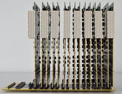
For the PETRA-III beamline at DESY, the group FEB has developed the complete operational electronics for a hydrostatic levelling system (HLS). The HLS is based on a long, horizontal pipe that is connected to beamguiding components of PETRAIII and that is filled to one half with water. At specific metering points, the water surface is measured by the generation of ultrasound pulses and the measurement of their reflections at the water surface. By a special reference system within the metering points three reflections are produced (see figure), which allows an automatic temperature compensation. The ultrasound reflections are measured with a 12-bit and 100MHz ADC, which allows a sufficient time resolution (better than 1ns) for accuracies of the measured water levels of about 1µm. The control electronics is based on ARM7 microcontrollers and fast FPGAs.
At PETRAIII, currently 130 metering points are successfully in operation. For the second phase of PETRAIII and FLASHII, 270 further metering points are in development with a new TCP/IP interface.


  • Full design of crates for 4 measurement stations

  • A microcontroller boards: ARM7 with CAN or ARM9 with Ethernet

  • A FPGA interfaced ADC and pulse board 100MS/s

  • Pulse generation of 100V into 50-Ohm

  • Reflection pulse readback of a few 10mV on same line

  • Time and position reconstruction within micro-controller


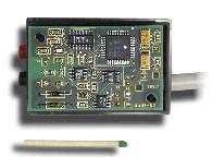
XNAP: Test board for a multichannel APD with readout ASIC

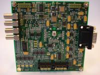
The board is designed as a cheap adapter to support a structure of an APD-area-sensor, an interposer and an ASIC.
This structure is connected with wire bonds to the board. The signals for the communication between the FPGA and the ASIC are converted to the required levels. Also the required voltages are generated from one input voltage and filtered to allow low noise operation.

The board is used by the ASIC developers to test ther performance of different generations of the ASIC's themselves. It was also used to test the whole essembly within an X-ray beam.

The PCB allows datarates above 400Mbits/s/line.


The responsibity of FEB was the design of the board.

Documents and further information
application/pdf Manual (152KB)
Manual

Fast Pulse Masker

For beam studies at VUVFEL it is required to kick out individual bunches. For these short time periods signals from a few photomultipliers have to be disabled. The basic functionalities of the electronics are:
  • Masking the signal for a period of 500ns after a rising edge of a TTL-input
  • Forbidding a second trial of masking during the next 90ms
  • Keeping the mean level of the input signal from the period (t=3.3ms) before the masking during the short term of the masking.
  • Slow drifting of the output to a 20mV level opposite to usual polarity, if a failure in the digital electronics keeps the masking for long periods.
  • (Pseudo-) differential analogue input to avoid ground loops,
  • Differential analogue output with gain 1, to reduce common mode currents and to keep the difference small between plugging the ‘Fast-pulse-masker’ into the cable from the photo multiplier to the following electronics or leaving it out.
  • 100-Ohm differential techniques for usage of LAN cables or twisted pair flat cables.
application/pdf User Manual (2.3 MB)
Fast_pulse_masker_user_manual.pdf
image/pjpeg Pictures from electronics (273KB)
FPM_crate_and_pcb.jpg

Laser synchronization to TTF1-Beam

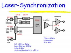
To measure optical effects synchronized to the bunches of the electron beam, pulsed lasers have to be stabilized in time. For measuring the longitudinal beam profile of TTF-I with electro-optical-sampling (EOS) electronics has been developed, which synchronizes the phase of a 81MHz infrared laser to the 1.3GHz master oscillator of the accelerator.


Reached synchronization: 0.2ps

application/msword Design description (372KB)
lasersync_design_description_002.doc
application/vnd.ms-powerpoint Principle of operation (1.0 MB)
Lasersync_principle.ppt

Beam Stabilizer for Photon Beams at HASYLAB (DMOSTAB)

HASYLAB provides X-ray test beams.The beam parameters are adjusted with a voltage supplied to a pieco-crystal. Changing the voltage turns a X-ray reflection crystal. This allows to control the beam intensity, the energy of the photons and the energy spread.

The operator defines the operating mode and set point via the front panel or RS232 terminal port. The electronics stabilizes the beam conditions for a long data aquisition time. The input signal is the beam intensity. A DSP scans the beam profile and calculates the voltage for the pieco-crystal.

application/pdf User Manual (228KB)
d_mostab.pdf

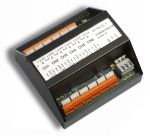
Multichannel Temperature Monitor and Alarm System for HERA

The beam pipe of HERA is strongly heated by synchrotron radiation. To avoid damages of the pipe, the temperature needs to be monitored and might have to trigger a beam dump. The sensors are distributed around the HERA-ring. So the electronics has to cope with varying ground potentials, long signal cables and routing of signal lines parallel to high current cables. Therefore electronics close to the sensors converts the temperature into a frequency. This allows to transfer the information over the long distances as digital signals. A phase locked counting avoids the pick up of noise from the 50Hz power lines.

Transient Recorder for HERA and PETRA

To optimize the performance of the HERA accelerator also rare effects like unusual voltages and digital patterns, temperatures etc. have to be monitored. Pulse shapes of corresponding signals have to be recorded before and after the time of identification. This is simultaniously done with a common time stamp at a large number of locations distributed over the whole areal of HERA. All data are written to a common archive and can be analyzed offline. The design can be upgraded to an infinite number of channels. Also a synchronization with the HERA revolution time is possible.

  • Sampling rate up to 100 kHz
  • Analog probes: 12 bit resolution, full scales from 0.1V to 30V
  • Digital probes: 12 bit patterns per probe, TTL-level or SPS-level
  • 8k Samples Storage Depth


Radiation monitors for D3

In the DESY areal in Hamburg and in future at the photon gun in Zeuthen the radiation level has to be monitored. Long term protocols are written to a data base and spikes or high levels interlock the operation of the accelerators.
The radiation level of photons is measured as current in ionization chambers. Neutrons are detected as pulses in proportional counters. The current in the ionization chamber is on the small level of 100fA. The neutrons generate a few pulses in a minute.
The developed electronics transform the current into a pulse rate. So the same digital electronics can handle photon and neutron detectors. From the pulse rate hard wired counters and a simple programmable gate area produce alarms on too high and too low rates. The count rates and the alarms can be read out via a CAN-bus. Designing the electronics with a careful look to power consumption allows to store counter values still in the moment of a power failure.