URL: https://fe.desy.de/sites/site_fe/content/fec/activities/characterization/20ghz_signals/@@siteview
Breadcrumb Navigation
High-Frequency Signals up to 20 GHz
|
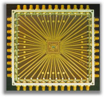
As integrated circuits increase in speed and complexity, the ability to test such circuits becomes more difficult. Fig.1 shows a corresponding test fixture for bare dies with up to 44 I/Os. Coplanar 50 Ohm transmission lines and SMA connectors form the electrical interface to external equipment. The device under test is attached to an chip-specific carrier which is placed in center region of the test fixture and connected by bond wires. High speed inputs are terminated by 50 Ohm chip resistors close to chip pads. |

Fig.1 |
|
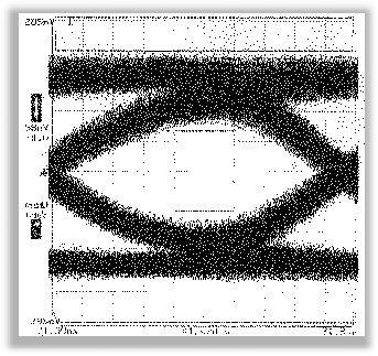
Here the result of a 4:1 multiplexer with PECL inputs is exemplary shown. Driven by a pseudo-random input bit stream a superposition of all occurring states within a data period at output is measured using a high-speed sampling oscilloscope (c.f. Fig.2). An OC-48 mask (ITU standard) is inserted and defines regions above, below and in the middle of measured eye that must not be touched by measured data points |

Fig.2 |


