
URL: https://fe.desy.de/sites/site_fe/content/fea/fea_projects/fast_control_system/@@siteview
Breadcrumb Navigation
Fast Control System for HERA-B
The FCS is a central part of the data aquisition system of the HERA-B experiment. It provides
- the distribution of the Bunch Crossing Pulses (every 96 ns) to more than 250 crates along the detector with high accuracy (jitter and skew < 500 ps)
- the filtering, sorting and distribution of the information generated by the First Level Trigger
- the handling and distribution of the Slow Control Commands like starting and stopping of runs, fine tuning of the timing signal delays, etc.
- the generation of statistical information and histograms about the accepted and rejected events
- different test features to generate triggers and test pulses to control the functioning of the data aquisition modules
The FCS contains several modules:
|
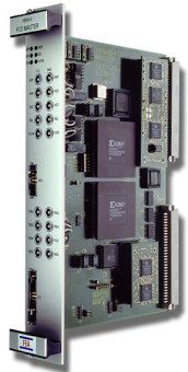
FCS Master Module |
|
|
This VME module receives the Bunch Crossing Signals from the HERA controls and the event trigger information generated by the First Level Trigger (FLT). Operator control is possible via the VME bus. |
|
|
FCS Fiber Transmitter Module |
|
|
This module receives the 20 bit data words and the clock pulse from the backplane, serializes the information via a HP-HDMP1012 chip, and drives (every 96 ns) the serial telegram via an 8-fold fanout into 8 optical fiber links (the drivers used are SIEMENS FC266). |

|
|
FCS Fiber Receiver Module |
|
|
This module receives every 96 ns the 20 bit long serial telegram via the optical fiber (the receivers used are SIEMENS FC266) , deserializes the information via a HP-HDMP1014 chip, and drives the parallel data and the clock pulse via a 10-fold fanout into 10 twisted pair cables (2x30, differential drivers DS90C031). This scheme allows the setup of up to 640 parallel data path (which all carry the same information, 20 data bits and one clock signal each). |

|
|
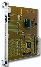
FCS Daughter Module |
|
|
This module works as a crate controler in a DAQ crate and receives every 96 ns the 20 data bits and the clock signal from the parallel twisted pair cable. The information is decoded, interpreted and used to drive the backplane according to the DAQ crate specifications. A programmable (via the FCS system) delay is used to synchronize all DAQ crates. Since the DAQ crates are not accessible during run time an additional CAN bus link allows the readout of a few bytes of information to verify the functioning of the FCS data transmission system. |
|